I spent a long night fighting a signal glitch with an STM32 PWM timer. Thought I’d share my story here so that others can benefit from my solution.
My patio lights use addressable LEDs (specifically the Lumex LX5050), and they expect a rather unique NRZ protocol. These LEDs are pretty particular: they really want to be signaled at 1.2uS/bit. Because each “bit” is actually comprised of either a 25% or a 75% duty cycle frame, any strategy involving a shift register must perform its shifts at 4x that speed, or 300nS/sub-bit – effectively clocking at 3.33MHz.
For my first attempt at controlling them, I built a controller board using a SPI port. Several others have had success with abusing the SPI protocol to make this work, but I didn’t have a great experience with it. The trouble is that SPI does not always offer very granular control over the bitrate.
On many MCUs, the SPI bitrate is a simple divisor of a system clock. On the STM32 MCU that I am using, the SPI port derives from a 30MHz APB peripheral clock, and the prescaler only allows subdividing that by powers of 2. The closest bitrate I could get was (30MHz / 8) or 3.75MHz. This gives a 1.06uS / bit speed, which is good, but apparently not quite good enough (12% out of spec). I frequently encountered bit errors that resulted in an LED going wildly off of its assigned color. I could have reprogrammed the APB clock, but since it is shared with other peripherals, that would have just kicked the can down the road to another peripheral.
FROM SPI TO TIMER
I re-spun my controller board with better power supplies, a dedicated level shifter to get a clean 5V translation from my 3.3V GPIO, and most importantly a control signal change to use a PWM timer instead of SPI. The STM32 timers have very good PWM support, so I expected to get really accurate timing. The only tricky part was that I had to change the PWM duty cycle from 25% to 75% or vice versa every 1.2uS – way too fast for an interrupt.
I decided to feed the STM32 timer’s capture compare from a DMA channel, and I’m not the first to try that either. I had no trouble getting the timing very, very precise. However I just traded one problem for another.
I started with this code to update just the first LED in the chain (note that the first argument, whichLED, is unused):
void WriteLED(int8_t whichLED, uint8_t r, uint8_t g, uint8_t b)
{
	memset(pwmData, 0, sizeof(pwmData));
	uint8_t mask = 0x80;
	for (size_t i = 0; i < 8; i++)
	{
		pwmData[i     ] = (r & mask) ? 27 : 9;
		pwmData[i + 8 ] = (g & mask) ? 27 : 9;
		pwmData[i + 16] = (b & mask) ? 27 : 9;
		mask = mask >> 1;
	}

	HAL_TIM_PWM_Start_DMA(&htim3, TIM_CHANNEL_1, (uint32_t *)pwmData, 100);
}

void HAL_TIM_PWM_PulseFinishedCallback(TIM_HandleTypeDef *htim)
{
	HAL_TIM_PWM_Stop_DMA(&htim3, TIM_CHANNEL_1);
}
Since my timer’s total count per cycle is 36, I use a value of 9 to get a 25% duty cycle (for a zero) or a 27 to get a 75% duty cycle (for a one). This basically works… kinda…
Except that if you look at this scope trace, you’ll see that it’s actually very glitchy.
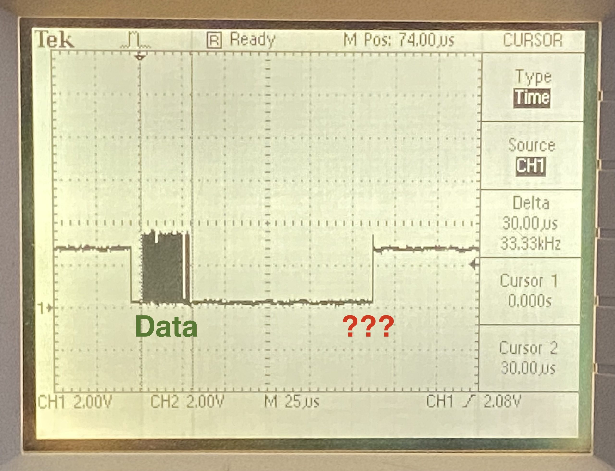
Notice that after the DMA transfer finishes, the control signal floats high. After the call to HAL_TIM_PWM_Stop_DMA(), the output apparently goes “undefined” (based on info in a couple of posts including this one).
I spent more than a day trying to resolve this. One suggestion online was to ensure that the GPIO is configured for pulldown. This did nothing. Another suggestion was to force the output after DMA completes via the CCMRx register. Again, this didn’t work for me.
I tried leaving the timer always on: not calling HAL_TIM_PWM_Stop_DMA, ever. The DMA was already configured for single-shot use, not continuous running. This only partially resolved the problem.
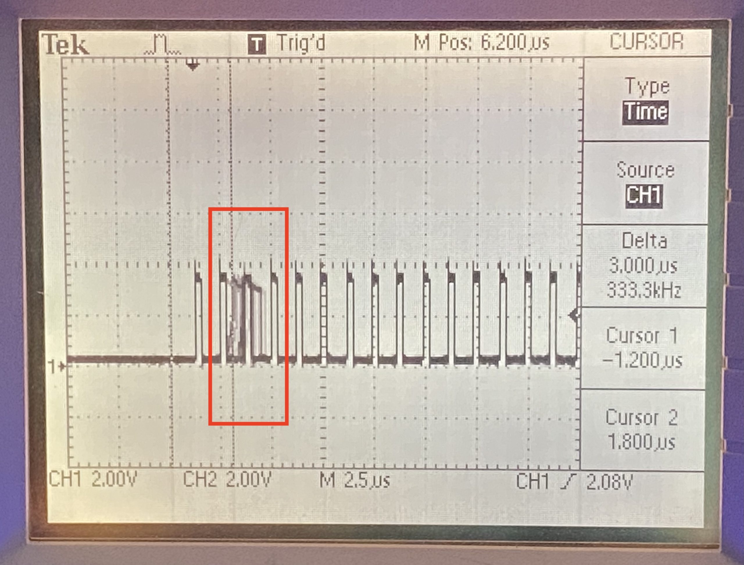
You can see in this photo that the first few bits are garbled. Apparently the HAL begins the DMA transmission and then interferes with the PWM channel once it starts.
Since the garbling always happens in the first few bits, I tried delaying the live data by just writing 24 bits of zeroes at the start of every transmission.
void WriteLED(int8_t whichLED, uint8_t r, uint8_t g, uint8_t b)
{
	memset(pwmData, 0, sizeof(pwmData));
	uint8_t mask = 0x80;
	for (size_t i = 0; i < 8; i++)
	{
		pwmData[i + 24] = (r & mask) ? 27 : 9;
		pwmData[i + 32] = (g & mask) ? 27 : 9;
		pwmData[i + 40] = (b & mask) ? 27 : 9;
		mask = mask >> 1;
	}
	HAL_TIM_PWM_Start_DMA(&htim3, TIM_CHANNEL_1, (uint32_t *)pwmData, sizeof(pwmData) / 2);
}
That didn’t work out well either. The glitch doesn’t happen in the middle of the bitstream, but it still happens – and it definitely confuses the LEDs.
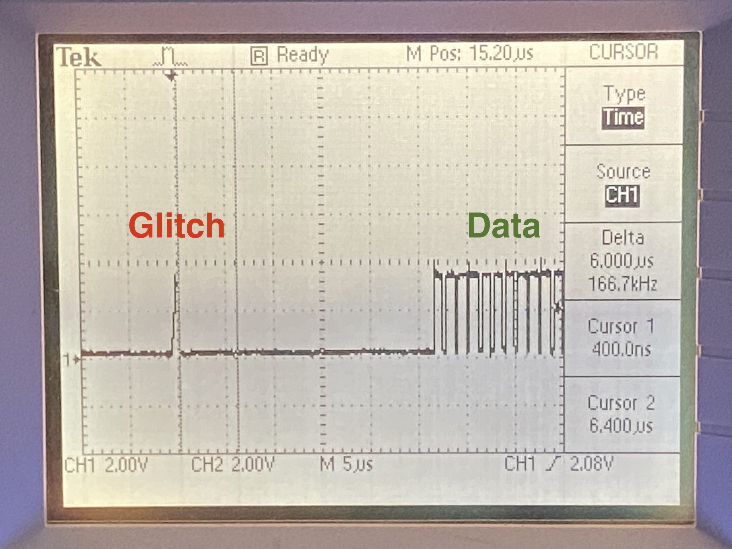
The ‘glitch’ is actually pretty consistent, and based on the slow risetime, it seems like the line is going to tristate.
For my next trick, I decided to move the I/O pin out of timer alternate-function mode and back to generic GPIO after transmission completed, and then move from GPIO to alternate function again just before starting a transmission.
void Timer3On() {
	GPIO_InitTypeDef GPIO_InitStruct = {0};
	GPIO_InitStruct.Pin = GPIO_PIN_6;
	GPIO_InitStruct.Mode = GPIO_MODE_AF_PP;
	GPIO_InitStruct.Pull = GPIO_PULLDOWN;
	GPIO_InitStruct.Speed = GPIO_SPEED_FREQ_HIGH;
	GPIO_InitStruct.Alternate = GPIO_AF2_TIM3;
	HAL_GPIO_Init(GPIOA, &GPIO_InitStruct);
}
void Timer3Off() {
	GPIO_InitTypeDef GPIO_InitStruct = {0};
	GPIO_InitStruct.Pin = GPIO_PIN_6;
	GPIO_InitStruct.Mode = GPIO_MODE_OUTPUT_PP;
	GPIO_InitStruct.Pull = GPIO_PULLDOWN;
	GPIO_InitStruct.Speed = GPIO_SPEED_FREQ_HIGH;
	GPIO_InitStruct.Alternate = GPIO_AF2_TIM3;
	HAL_GPIO_Init(GPIOA, &GPIO_InitStruct);
	HAL_GPIO_WritePin(GPIOA, GPIO_PIN_6, GPIO_PIN_RESET);
}
void WriteLED(int8_t whichLED, uint8_t r, uint8_t g, uint8_t b)
{
	memset(pwmData, 0, sizeof(pwmData));
	uint8_t mask = 0x80;
	for (size_t i = 0; i < 8; i++)
	{
		pwmData[i + 24] = (r & mask) ? 27 : 9;
		pwmData[i + 32] = (g & mask) ? 27 : 9;
		pwmData[i + 40] = (b & mask) ? 27 : 9;
		mask = mask >> 1;
	}
	HAL_TIM_PWM_Start_DMA(&htim3, TIM_CHANNEL_1, (uint32_t *)pwmData, sizeof(pwmData) / 2);
	Timer3On();
}
void HAL_TIM_PWM_PulseFinishedCallback(TIM_HandleTypeDef *htim)
{
	HAL_TIM_PWM_Stop_DMA(&htim3, TIM_CHANNEL_1);
	Timer3Off();
}
You’ll notice that I left the beginning of the buffer empty as before. After calling HAL_TIM_PWM_Start_DMA, it takes a few microseconds for Timer3On() to get the GPIO back into alternate function mode. If data bits are already streaming at that time, the leading edge of the data gets truncated. By reserving the first few bit positions, this isn’t really a problem.
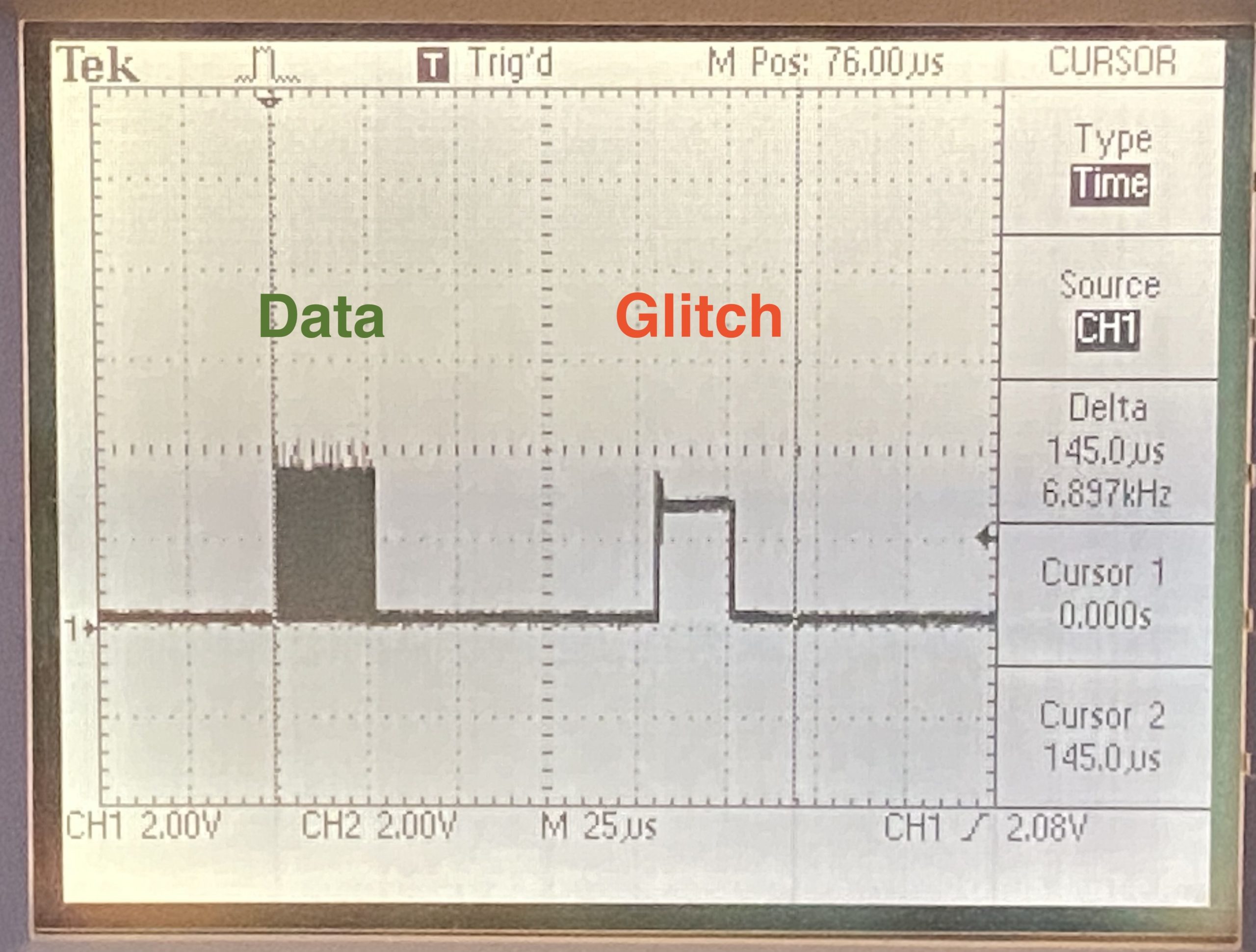
I still didn’t expect this to work, and I was correct. The problem, of course, is that once I call HAL_TIM_PWM_Stop_DMA(), the line is already transitioning to high state before Timer3Off() can switch the pin into GPIO mode.
The final step was to call Timer3Off() before calling HAL_TIM_PWM_Stop_DMA():
void HAL_TIM_PWM_PulseFinishedCallback(TIM_HandleTypeDef *htim)
{
	Timer3Off();
	HAL_TIM_PWM_Stop_DMA(&htim3, TIM_CHANNEL_1);
}
This works brilliantly. As a practical matter, I just set aside the first 24 bits (one LED’s worth of bits) to always be zero. The last 50 bits are already reserved as zeroes anyway, to provide the end-of-transmission signal. So using both leading and trailing zeroes does not bother me much.
I cleaned this up with named constants and other engineering niceties, and I’ve used it with great success ever since. A caution: don’t allow interrupts between DMA startup and Timer3On(), or else the switch back to AF mode could be delayed until transmission has already begun.
This isn’t quite as robust as I would like, but then again, neither is the behavior of this timer in the first place.
Leave a Reply
You must be logged in to post a comment.